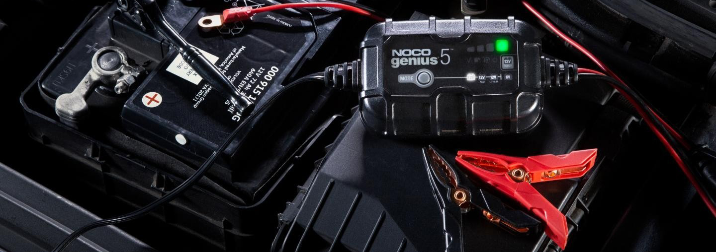
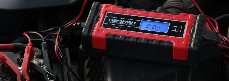
Car owners don't usually pay attention to the car battery. It could last longer with a little extra care. It could save you money, reduce waste and give you peace of mind. The voltage regulator is a crucial component in the charging system. What do you know about it?
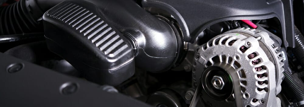
The alternator in a car is driven by the engine through the fan belt. As the engine speed varies over a wide range during running, the alternator speed varies accordingly, and the voltage will also vary over a wide range.
The working voltage of the car's electrical equipment and the battery's charging voltage are constant, usually 12V, 24V or 6V.
Therefore, when the engine is running, the alternator's output voltage should be kept constant in order to ensure the normal working of the electrical equipment and the battery. The generator is generally regulated at 13.5 - 14.5V (or 13.8 - 14.8V).
Consequently, the alternator must be equipped with a voltage regulator to keep the voltage at the terminal constant when the alternator speed varies. The alternator voltage changes with the alternator speed so that it remains constant.
When the alternator is working, the voltage regulator regulates the magnetic field flux by adjusting the current passing through the excitation winding after the alternator voltage exceeds a certain value, keeping the terminal voltage at the specified value.
The contact oscillating voltage regulator, referred to as a contact voltage regulator, is a mechanical voltage regulator which includes various types, such as single-stage contact, double-stage contact and contact with charging relays.
The basic principle is to maintain a constant alternator voltage by varying the opening and closing times of the contacts and changing the excitation current based on the alternator speed.
Due to its large size, contact easy to be burnt, large mechanical inertia, regulated voltage fluctuation amplitude, and other shortcomings, the transistor and integrated circuit electronic voltage regulator have gradually replaced this type.
The transistor type uses the switching action to control the on/off of the alternator excitation circuit, regulating the excitation current and pole flux to maintain a constant voltage after the alternator speed has exceeded a certain value.
The integrated circuit voltage regulator is similar to the transistor type, but all the components in an integrated circuit regulator are made on the same semiconductor substrate, forming a separate, mutually indivisible electronic circuit.
Integrated circuit regulators are small, reliable and maintenance-free. They are widely used in modern vehicles.
This type of regulator can be installed inside the alternator or on the housing due to the small size and simple external structure, forming a complete charging system with the alternator and simplifying the structure of the charging system.
The regulator that is mounted inside the alternator is called an internally mounted regulator. No matter where the regulator installs (inside or on the alternator), the alternator is the integral type.
Turn on the ignition switch. The battery voltage is applied to the magnetic field terminal "F" of the alternator and, via the "+" terminal, to the two terminals of the voltage divider R1 and R2. The voltage regulator VS1 is subjected to the reverse voltage.
Both ends of the voltage divider exist the battery voltage. The value is lower than the alternator's regulating voltage. The voltage on both ends of the voltage regulator VS2 is also lower than its reverse puncture voltage. VS2 has the same working state as VT1.
The potential at point "b" is close to the power supply potential, so that diode VD2, triode VT2 and VT3 conduct. Next, the circuit of the alternator's excitation winding is turned on. The alternator establishes a magnetic field and starts to generate electricity.
As the alternator speed rises, the voltage rises. The voltage acting on the voltage divider and the reverse voltage across the voltage regulator rises.
When the alternator voltage is slightly higher than the specified regulation voltage, VS2 is reversely breakdown and conducts, and the triode VT1 also conducts.
After VT1 conducts, the potential at point "b" drops to near zero potential. Diode VD2 and triodes VT2 and VT3 cut off the alternator excitation winding circuit. The excitation current is interrupted. The magnetic field disappears rapidly, and the alternator voltage drops.
When the alternator voltage drops slightly below the specified regulation, the voltage regulator VS2 is cut off. The voltage rises again to remain constant when the alternator speed changes.
As we can see, when the engine is working, the voltage regulator is composed of resistors R1, R2 voltage divider to feel the change in alternator voltage.
The system uses the switching action of the regulator and transistor to control the excitation circuit, adjust the generator excitation current and pole flux, and keep the voltage constant after the alternator speed exceeds a certain value.
Volkswagen
Volkswagen uses the JFZ1913Z and JFZ1813Z integral alternators, rated at 1.2 kW. The alternator has two terminals, and the output terminal is connected directly to the battery's positive terminal for external power supply.
The magnetic field terminal connects to the positive battery terminal via a diode, charge indicator, fuse and ignition switch. It supplies the alternator with the excitation current and controls the charge indicator.
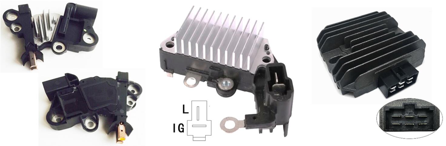
The regulator uses the "alternator voltage detection" method. It connects, via 3 terminals, to the alternator's excitation diode output, brushes and case respectively.
Turn on the ignition switch. The battery supplies the alternator with the excitation current and the voltage to the control section via the ignition switch, fuse, charge indicator and diode.
The battery voltage falls below the upper limit of the regulation voltage. The regulator turns the excitation circuit on, and the charge indicator light comes on. The excitation circuit and the charge indicator circuit are as follows.
Positive battery terminal - ignition switch - fuse - charge indicator - diode - excitation winding - regulator - latch - negative battery terminal.
As the engine speed increases, when the alternator terminal voltage exceeds the battery terminal voltage, the alternator starts to self-excite and charge the battery. It provides voltage to the detection and control section.
The charge indicator goes out because the voltage at both ends is almost zero, indicating that the alternator is working properly. If the voltage at terminals has not yet risen to the upper limit of the regulated voltage, the regulator turns the excitation circuit on.
The self-excitation circuit is: alternator stator winding - excitation diode - excitation winding - regulator - lap iron - negative tube - alternator stator winding.
When the alternator's terminal voltage is higher than the upper limit of the regulator's regulation voltage, the regulator disconnects the excitation circuit. The alternator flux is weakened, and the terminal voltage is reduced.
When the terminal voltage falls below the lower limit of the regulator voltage, the regulator turns the excitation circuit on, and the alternator voltage rises. The regulator continuously controls the excitation circuit to keep the alternator voltage from exceeding the regulator's regulated voltage.
The diode in series with the charging indicator is to ensure that the alternator does not supply power externally through the excitation diode and the charging indicator when the terminal voltage is higher than the battery terminal voltage. Otherwise, the charging indicator will be illusory to the driver. The excitation diode will be damaged by overload.
 Lauritz Carolsfeld
  March 18, 2022