
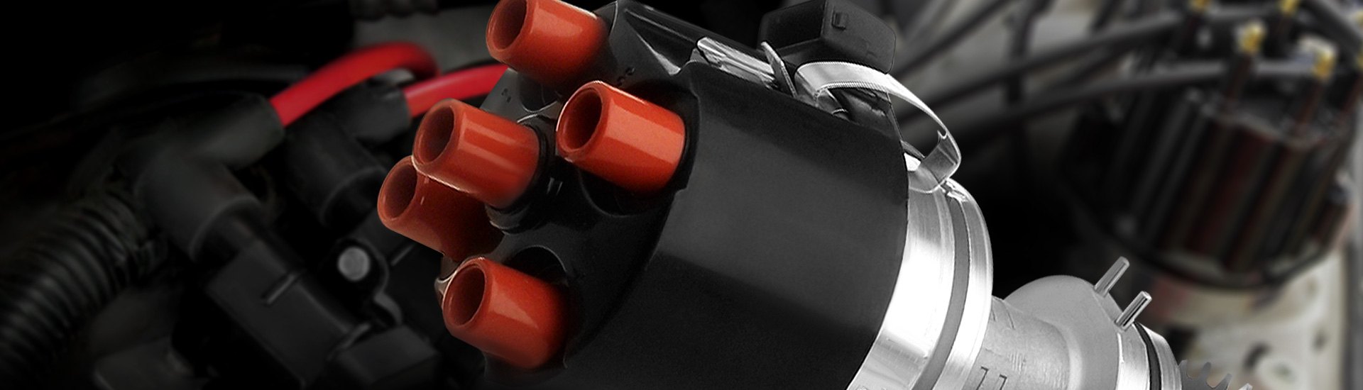
The distributor is a component of the ignition system. It controls the primary circuit in time and distributes the spark to each cylinder in sequence. The distributor is mainly used in the traditional ignition system and the electronic ignition system. However, these two ignition systems have been basically eliminated.
1.3 Photoelectric induction type
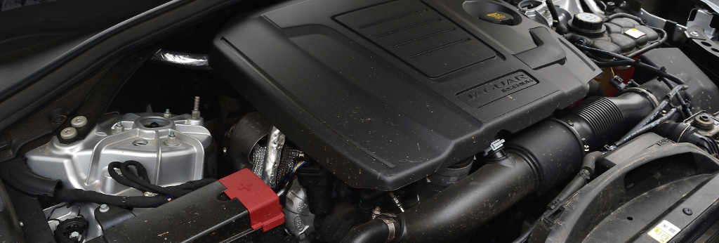
Nowadays, more and more distributorless ignition systems exist in automobile engines. We can only find distributors in old and used cars.
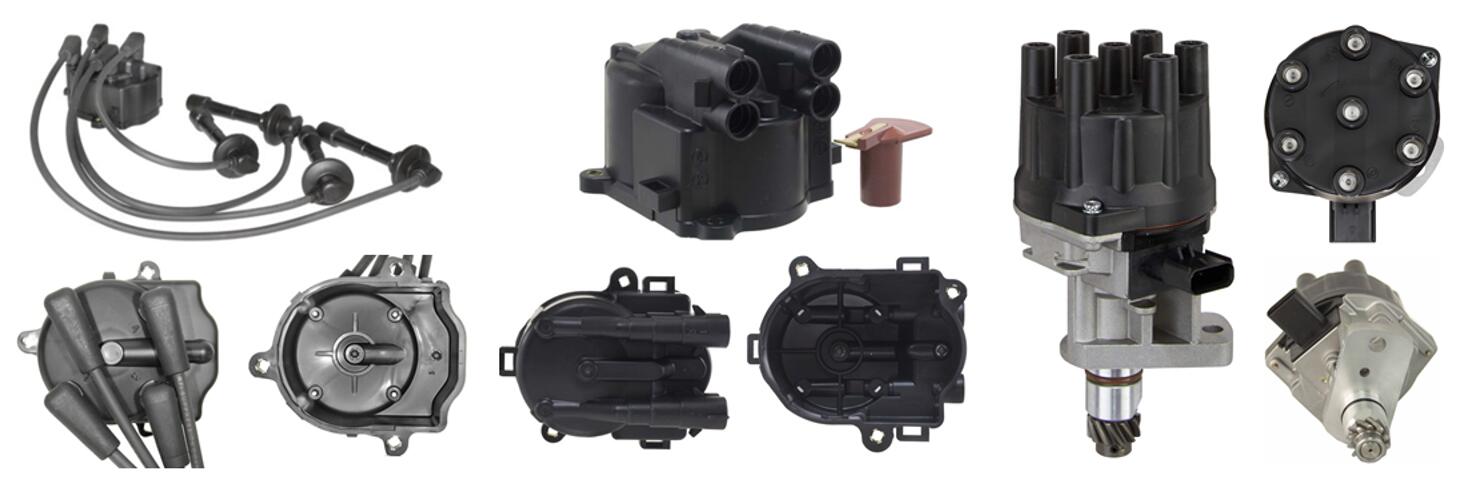
There are many types of distributors, but the internal structure and working principle are basically the same. They all consist of the signal generator, distributor cap, rotor, and centrifugal ignition advance device.
The function of the signal generator is to generate signal voltage to the ignition controller. It controls the work of the ignition system through the ignition controller.
According to the working principle, the signal generator can be divided into magnetic induction type, Hall type, photoelectric induction type, and electromagnetic oscillation type.
The magnetic induction signal generator mainly consists of a signal rotor, permanent magnet, induction coil and standoff frame. The working principle of the magnetic induction signal generator is as follows.
The signal rotor of the signal generator has the same number of teeth as the engine cylinder. When the signal rotor rotates, the air gap between the teeth of the signal rotor and the core changes. The magnetic flux through the sensing coil also changes.
The induction alternating electric potential is generated in the sensing coil. The alternating electric potential is input to the ignition to control the system.
When the signal rotor is in the process of rotation, the flux change is very regular. The air gap between the rotor teeth and the coil core is the largest.
The magnetic flux in the coil is the smallest. And the flux change rate is equal to 0. At this time, no induced electric potential is generated in the coil.
As the teeth gradually approach the core, the magnetic flux in the coil increases. When the teeth reach a specific position, the rate of increase of magnetic flux in the coil reaches the maximum. The changing rate of the magnetic flux reaches the maximum.
At this time, the maximum induced electric potential is generated in the coil.
As the rotor continues to rotate, the rate of increased flux in the coil decreases. When it reaches a specific position, the flux in the coil reaches its maximum. However, the changing rate of flux at this time is 0. The induced electric potential in the coil is also equal to 0.
The magnetic flux gradually decreases after the cam tooth turns over the core position. When it reaches a specific position, the reduced flux rate reaches the maximum.
At this time, the rate of changing flux reaches the maximum. And the reverse electric potential induced in the signal induction coil is at the maximum.
The advantage of the magnetic induction signal generator is that it is simple in structure and can be adapted to various environments.
The disadvantage is that the signal voltage increases with the increase of the speed and decreases with the decrease of the speed. When the engine speed is low, the signal voltage is low, which is not good for engine starting.
The Hall signal generator works by using the Hall effect. The Hall effect was discovered by the American scientist Hall in 1879.
The basic principle is that when the current is passed through a semiconductor substrate placed in a magnetic field, and the direction of the current is perpendicular to the direction of the magnetic field, a voltage proportional to the strength of the current and the magnetic field is generated on the lateral side of the semiconductor substrate perpendicular to the current and the magnetic field. This voltage is called the Hall voltage.
The Hall signal generator is mainly composed of a trigger impeller integrated with the distributor shaft, Hall integrated circuits, permanent magnets with conductive plates and special sockets.
The trigger impeller has same number of blades as the engine cylinder. The trigger switch board is made with Hall integrated circuit and permanent magnet with magnetic plate.
The outer layer of Hall integrated circuit is Hall element. Other parts of the same substrate are made into amplifier circuit.
The working principle of the Hall signal generator is as follows. The distributor shaft drives the trigger impeller to rotate. When the blade enters the air gap between the magnet and the Hall element, the magnetic field is bypassed and the Hall element does not generate Hall voltage.
When the trigger impeller leaves the air gap, the magnetic lines of force of the permanent magnet pass through the Hall element and generate Hall voltage.
The signal from the Hall voltage is weak (only in the mV range). So it must be amplified. The amplified signal controls the on and off of the output transistor.
When the Hall element does not produce the Hall signal, the output transistor is cut off. The detection signal input by the ignition is at a high level (close to the supply voltage, about 9V).
When the Hall element generates a Hall signal, the triode at the output is in conduction. The detection signal input by the ignition is at a low level (about 0.4V).
1.3 Photoelectric induction type
The photoelectric induction signal generator mainly comprises a light-emitting element, a photosensitive element and a masking rotor. The light-emitting and photosensitive elements are located on opposite sides of the shading rotor.
The shading rotor is fixed on the camshaft and rotates together with the camshaft. When the shading rotor blocks the light from the light-emitting element, the photosensitive element cuts off and the control circuit outputs a low level.
When the slit is aligned with the light-emitting and photosensitive elements, the light shines onto the photosensitive element and the control circuit outputs a high level.
When the camshaft turns one cycle, the circuit controlled by 360 slits will output 360 pulse signals. This signal is used as the speed signal input to the computer.
The disadvantage of the photoelectric signal generator is the poor anti-pollution ability. The light-emitting components and photosensitive components will be affected by the contamination of the signal voltage. This generator is far less widely used than the first two signal generators.
The distributor cap and rotor are mounted on the upper part of the signal generator. They serve to distribute the high voltage to spark plugs in the order of ignition.
The distributor cap is made of hot-pressed gumwood powder in a steel mold. It is mounted on the top of the distributor and fastened with two elastic clips. The rotor is mounted on the top of the distributor shaft. It rotates with the shaft. A conductive metal sheet is attached to it.
The middle of the distributor cap has a high-voltage wire seat hole equipped with a spring carbon column pressed on the conductive piece of the distributor cap.
The distributor cap is surrounded by the number of cylinders of the engine equal to the number of by-pass electrodes to the cover of the metal sleeve seat hole in order to insert the ignition cable. When the rotor rotates, the conductive piece crosses the gap of 0.2~0.8mm from the side electrode.
When the signal generator generates the ignition signal, the high voltage jumps from the conductive piece to the side electrode. It is sent to the spark plug via the high voltage line of the sub-cylinder.
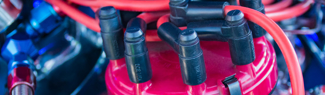
There are two types of high voltage wires: central high voltage and sub-cylinder high voltage. Generally, it is a copper-core wire or all-plastic high-voltage damping wire with pressure-resistant insulation cladding.
It is often arranged vertically and horizontally to avoid breakage, length reduction, high voltage resistance to extend service life.
The function of the centrifugal regulator is to adjust the ignition advance angle by using centrifugal force to automatically advance the ignition signal from the signal generator when the speed changes.
There are pallets fixed on the distributor shaft. Two heavy blocks are set on the pins of the pallets. The other ends of the heavy blocks are pulled by springs toward the shaft center.
The rotor of the signal generator is set on the distributor shaft together with the pallets, which have long holes at both ends and are set on the pins of the centrifugal blocks.
When the ignition advance angle does not need to be adjusted, the centrifugal regulator is in the inactive position. The two centrifugal blocks are held to the shaft by the tension spring. When the engine speed increases, the two centrifugal blocks are thrown outward by centrifugal force.
The pin on the centrifugal block pivots the paddle and the generator rotor, which rotates at an angle relative to the shaft in the direction of rotation of the distributor shaft, generating an ignition signal in advance and increasing the ignition advance angle.
The higher the rotational speed, the greater the centrifugal force of the centrifugal block, the greater the ignition advance angle. Conversely, the rotation speed decreases, and the ignition advance angle decreases.
For more expert tips and advice on engine maintenance, take a look at our other articles here on the Delcoribo blog.
The role of the vacuum regulator is to automatically adjust the ignition advance angle when the engine load changes. It is mounted on the side of the distributor housing.
There is a diaphragm made of elastic metal sheet fixed in the shell. The center of the diaphragm is fixed with the tie rod on one side. And the other side is pressed with a spring. The tie rod extends from the shell base hole.
It is connected to the base plate and pulls the base plate to carry the stator of the signal generator to produce angular displacement with respect to the shaft.
When the engine load is small, the throttling threshold is also small, the vacuum below the throttle and the pipe increases. The vacuum suction attracts the diaphragm to compress the spring and arch.
At the same time, the bottom plate is pulled by the tie rod to carry the stator of the signal generator to turn a certain angle against the direction of distributor shaft rotation.
The ignition signal is generated earlier, so the ignition advance angle increases. The smaller the load, the smaller the throttling threshold, the higher the vacuum, the larger the ignition advance angle. And conversely, the larger the load, the smaller the ignition advance angle.
 Lauritz Carolsfeld
  December 06, 2021