
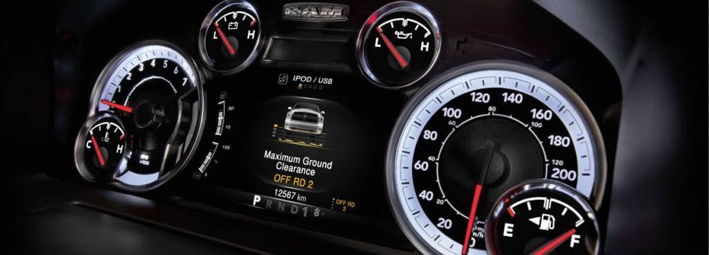
The engine control unit (ECU) is generally equipped with fault self-diagnosis and protection functions. It also automatically records fault codes in RAM when a system fault occurs. These messages are displayed on the dashboard and remain there, allowing the owner to identify the problem and take the car to a repair shop.
3.5 Input stage and output stage
The working principle of the electronic engine control system is that when the engine starts, the ECU quickly goes to work. Some certain programs or steps are taken out of RAM and into the central processing unit (CPU). This process can control fuel injection, ignition timing and idling.
One command signal after another is cycled through the control of the CPU. The required engine information comes from various sensors during the program's execution. The signals first enter the input stage (loop), where their signals are processed.
According to the CPU arrangement, if the signal is digital, it enters the ECU via the input/output (I/O) interface circuit. If it is analogue, it has to be converted into a digital signal by an A/D converter before entering the ECU via the I/O interface circuit.
Most of the information is stored temporarily in RAM, from which the instructions are sent to the CPU as required. The reference data is also sent to the CPU in the next step. It will be compared with the signals from the sensor inputs.
Each signal from the sensor is also sampled in turn and compared with the reference data.
After this process, the CPU makes a decision and issues a control command output signal, which is converted into an analogue signal by the I/O interface circuit, for some necessary signals, by A/D conversion. Finally, the output stage (circuit) controls the actuator.
If it is the drive signal of the injector, it controls the injection timing and injection pulse width to complete the control of the injection function.
The ignition timing signal controls the on and off of the ignition coil to make the secondary produce high voltage to break through the spark plug gap to generate sparks.
The ECU's calculation speed is quite fast when the engine is running. For example, the ignition timing can be corrected hundreds of times per second so that the control accuracy can be high.
The input circuit sends the signals detected by the sensors in the system to the ECU through the I/O interface circuit interface to complete the task of real-time detection of the operating conditions of the car engine during working.
There are two types of signal to be detected and input: analogue and digital. The signal from the sensor input first enters the input loop, where it is pre-processed to remove spurious waves and change the sine wave into a rectangular square wave before being converted into an input level.
The ECU is the core of the engine's electronic control system. With the rapid development of automotive electronics, ECU is constantly updated, and nowadays, all cars use digital ECU.
The ECU can take the signals from the various sensors as required, pre-program them with memory programs (the sequence in which the ECU carries out processing) and data.
It stores the information in the memory so that the corresponding programs can be activated by the sensors when in use to achieve automatic control.
The automotive ECU only requires a certain capacity of semiconductor memory to meet the memory requirements. No external memory is required. In ECU, many detection elements (e.g., sensors) and instruments are used to collect and detect various parameters.
It is used to transform the detected parameters from non-electricity to electricity, such as thermocouples turning temperature signals into voltage (mV) signals, pressure sensors turning pressure signals into voltage signals, etc.
These signals are converted into a uniform standard voltage and then sent to the ECU for comparison and arithmetic processing. The accuracy of the detection elements thus directly determines the control accuracy of the entire control system.
In order to translate the commands and instructions from the ECU's calculation and processing results (e.g., injector injection signals, ignition timing signals, etc.) into control actions and movements and to implement them, the ECU needs to be equipped with actuators.
Commonly used actuators are electric, hydraulic or pneumatic types, such as stepper motors, solenoid valves, etc.
The CPU is the heart of the entire control system. It consists of arithmetic/logical operators, registers for the temporary storage of data, and controllers for signal transmission. The last one controls tasks between devices according to their degree.
The CPU works under the operation of a clock pulse generator. When the ECU is energized, the pulse generator immediately generates a series of pulse-width voltages with a certain frequency and sends them to the CPU. The whole process is to control the ECU at any time.
The RAM is mainly used to store programs, data and tables, maps, etc. That information can be read or deposited as required. The RAM consists of a number of memory cells.
Each one has a number called a cell address. Each cell usually holds a code with a separate meaning, called a word. The number of coded bits is called the word length.
The RAM is mainly used to store variable data during the work of the ECU, such as temporary storage of information input by the ECU for the CPU to carry out calculations, such as information delivered to the ECU by sensors on the vehicle.
Furthermore, intermediate data generated during calculations can be temporarily stored in the RAM and can be called out or replaced (rewritten) by new data at any time as required.
Some of the data stored in RAM, such as air-fuel ratio corrections, fault codes, etc., are generally connected directly to the battery via a special power backup circuit to be stored for a more extended time.
It prevents data loss due to the power being cut off when the ignition is switched off so that the ignition switch does not control RAM.
Of course, the data stored in RAM will naturally disappear when the dedicated circuit for power back-up is disconnected or when the power cable is disconnected from the battery.
The I/O interface circuit is the control circuit for exchanging information among the CPU, the input sensors and output actuators. On command from the CPU, the signals input to the ECU is received at the required frequency via the I/O interface circuit.
On the other hand, the signals output from the ECU are also output or sent to intermediate memory via the I/O interface circuit at the optimum processing speed in the form and as required by the control signals issued.
The external I/O devices used in ECU systems are generally equipped with I/O interfaces, which can only be connected to the ECU through the I/O interface.
Therefore, the I/O interface links the ECU and the controlled object for information exchange and is an indispensable part of the ECU system. It plays various roles such as data buffering, voltage matching and timing matching.
Looking for more information about automotive engines? You can get everything in our blog.
The ECU system bus is a bundle of wires that transfer internal information. In this system, the CPU, memory (ROM, RAM), and I/O interfaces are connected by a bus passing information.
The system bus generally consists of three parts: the data bus, the address bus and the control bus. The system bus uses data, storage addresses and control signals to operate and control the components in the system.
At the same time, the memory and I/O functions of the system can be expanded by using the connection bus.
3.5 Input stage and output stage
In addition to the ECU, there are external devices that make up the input and output stages in the ECU. External devices are I/O devices that connect the ECU and the application object.
The role of the input stage is to send the signals detected by the sensors in the system through the I/O interface circuit to the ECU for processing and to complete the real-time detection of the operating conditions of the vehicle engine.
There are two types of signals to be detected and input during the control process: analogue signals and pulsed digital signals.
The external input devices are the various sensors installed in the electronically controlled fuel injection engine (e.g., sensors for intake air temperature, mass air flow, engine coolant temperature, etc.), which send the detected information into the ECU for processing.
The output stage establishes a link between the ECU and the actuators, such as injectors and ignition coils, transforming the decision commands made by the ECU after processing the information into control signals to drive the actuators to work (action).
This thing works as a signal controller and amplifier, from which three control signals are output: the injector drive signal, the fuel pump drive signal and the ignition timing control signal.
The external output devices are the individual actuating elements of the fuel system and the ignition system (e.g., electric fuel pumps, solenoid injectors, ignition coils, etc.) The ECU can be further extended with output stages for additional applications.
 Lauritz Carolsfeld
  January 03, 2022