
Sensors are the input devices of the car computer. They transform various information, such as the car speed, temperature, engine operating conditions, into electrical signals. The computer receives and analyzes them. This process ensures that the vehicle is in the best working state.
So how should we test sensors? Let's take a look.
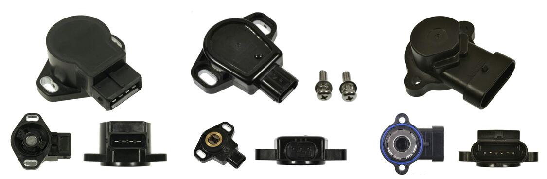
① Remove the connector plug of the throttle position sensor. Measure the resistance between the signal output pin and the ground pin with the multimeter. Slowly change the throttling threshold. The resistance value should increase continuously with the throttling threshold. There is no sudden change in the middle.
② Measure the resistance between the IDL contact signal pin and the ground pin. When the throttle closes, the resistance is 0 Ω. The resistance tends to infinity as the throttling threshold opens to the maximum.
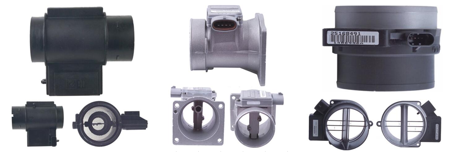
2. Signal voltage of mass air flow sensor
①Remove the mass air flow sensor. Add the battery voltage between the terminal power supply of the flow meter and the ground pin. Then measure the voltage. The standard value is between 1.1 and 1.2 V.
② Blow air into the air intake of the sensor. At this time, measure the signal voltage between the output terminal and the ground pin. The voltage should be 2.4 V.
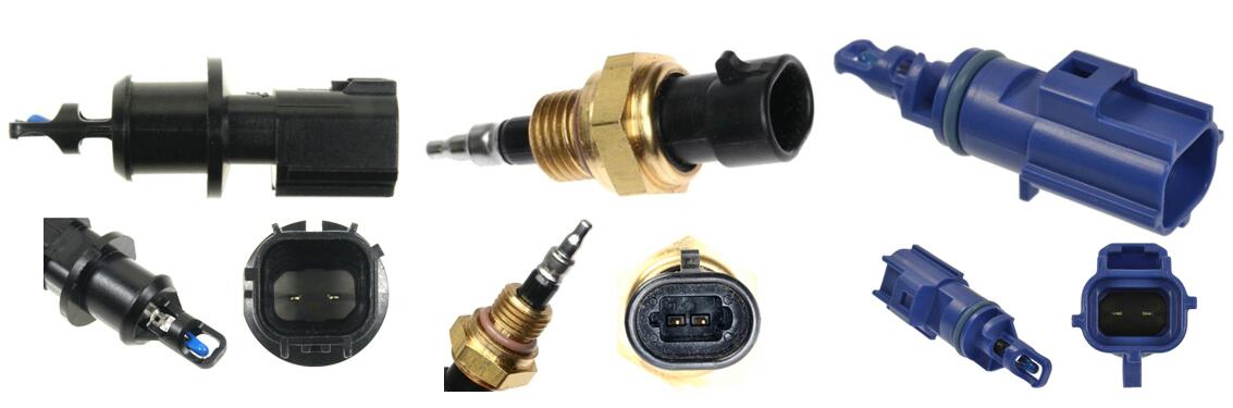
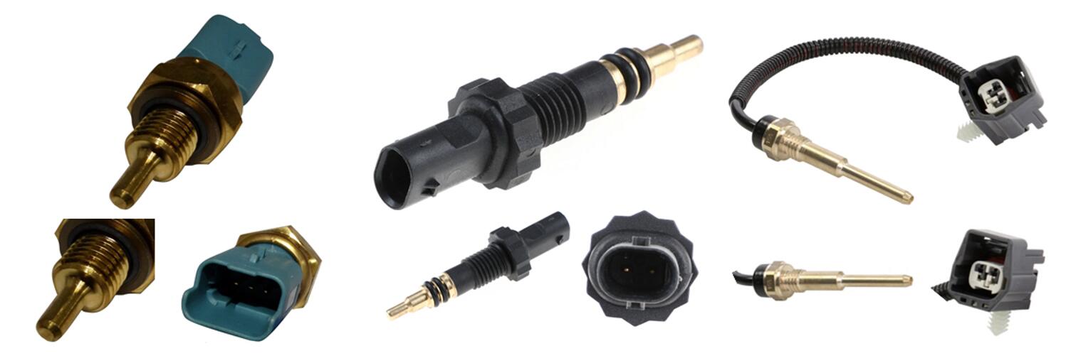
3. Intake air temperature sensor
Put the intake air temperature sensor in the heating water. To the negative temperature coefficient sensor, measure the resistance value with a multimeter. If the resistance is inversely proportional to the water temperature, the sensor is good. If the value doesn't change, the IAT sensor has been damaged.
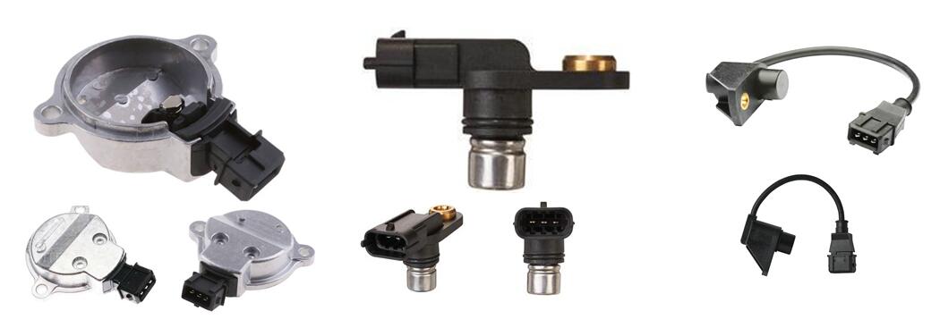
When the engine is running, test the signal waveform between the signal output terminal and the ground pin with an automotive oscilloscope.
For the high performance camshaft position sensor, the waveform should be a sawtooth square shape. The amplitude should be between 0 and 5V. As the engine speed increases, only the waveform frequency should increase. The amplitude shouldn't change.
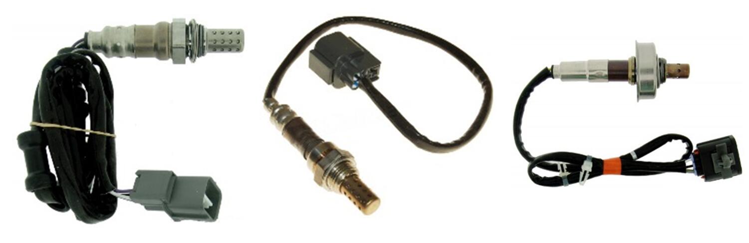
Start the engine and run to the normal temperature. Make the engine runs at the speed of 2500 rpm for more than 2 min. Keep the rate, then set the multimeter to the DC voltage range.
Measure the signal voltage between the terminal of the sensor signal output and the ground pin. The value should constantly change between 0.1 - 0.9V.
The continually changing signal voltage ( up and down 0.45V ) in 10s shouldn't be less than 8 times. Otherwise, the oxygen sensor is defective.
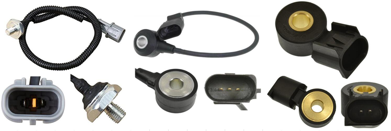
6. Knock sensor
Turn the ignition switch to the 'ON'. Don't start the engine. Test the signal waveform between the terminal of the sensor output and the ground pin with an automotive oscilloscope. Then knock the cylinder near the sensor with a metal object.
After the knocking, the oscilloscope should show an outburst waveform. The larger the knock, the larger the amplitude is, which means the sensor is fine. If the oscilloscope shows a straight line, that the knock sensor has no signal output. There may be an open circuit in the wire, or the sensor is damaged.
Turn the ignition switch to 'ON'. Remove the vacuum hose. Connect the hose to the manual vacuum pump. Measure the signal voltage between the terminal signal output and the ground pin with a multimeter.With the increasing vacuum, the signal voltage should be within the specified range. There is no sudden change.
We have other engine pressure sensors to sell online. If you require any help, just contact us.
8. Colour of oxygen sensor tip
Remove the oxygen sensor from the engine exhaust pipe. Observe the colour of the exhaust gas side.
① Light grey tip. This is the normal colour of the oxygen sensor.
② White tip. It is caused by silicon contamination. The oxygen sensor fails.
③ Brown tip. It is caused by lead contamination. The oxygen sensor fails.
④ Black tip. The carbon deposit causes it. After removing the carbon deposit, this problem can be solved accordingly.
In orer to identify bad water temperature sensor, turn on the ignition switch. Measure the signal voltage between the sensor THW and the ground E2 with a multimeter. This value should be the same as the signal voltage of the engine.
Put the thermometer close to the water tank. Start the engine ( cold start ) and test the signal voltage at different water temperatures. They should meet the specified requirements.
Check if the sensor head is dirty. Check if the gap between the sensor head and the gear ring complies with the rule. Check if the gear ring is defective (e.g., cracks, missing teeth and broken teeth). Check if the resistance value of the solenoid coil is following the standards.
11. ABS wheel speed sensor ( Oscilloscope )
Remove the connector plug of the ABS wheel speed sensor. Jack up the vehicle and turn the wheel. Test the signal waveform between the two pins of the sensor with an automotive oscilloscope.
You want to check if the ABS wheel speed sensor works properly. If so, the wheel speed, the frequency of the signal waveform and the amplitude are in direct proportion.
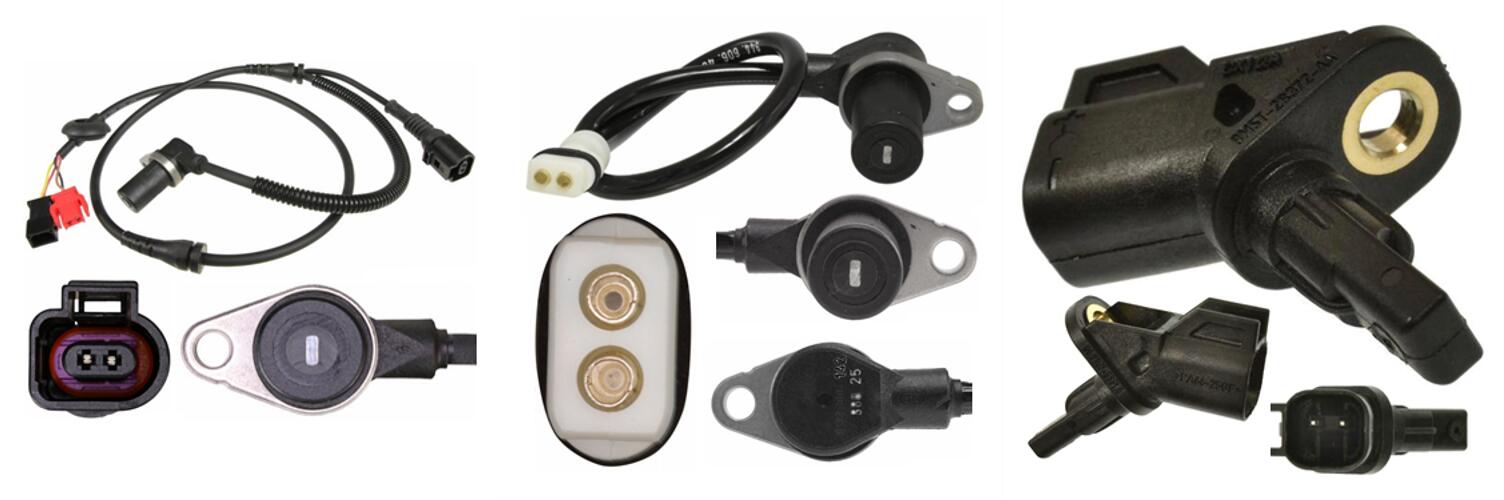
12. ABS wheel speed sensor ( Resistance measurement )
Remove the connector plug of the speed sensor. Measure the resistance value between the two terminals with a multimeter. Set the multimeter in the 'R × 100Ω' range. The resistance value should be consistent with the standard value.
Then test the conductivity between each terminal and the metal body. Under normal conditions, it shouldn't be conductive. Otherwise, the bond strap of the sensor is faulty.
Failure analysis of the ABS wheel speed sensor isn't an easy job.
13. ABS wheel speed sensor ( Signal measurement )
Connect the oscilloscope to the ABS wheel speed sensor. Drive the car at the speed of 20km/h ( or jack up the vehicle and turn the tested wheel ). Measure the output waveform voltage of the wheel sensor. It should be larger than or equal to 0.5V. Otherwise, the gap needs regulation. Or the sensor requires a replacement.
14. Potential point-of-failure in ABS System
① The functional failure of the CPU in the electronic brake control module ( EBCM ).
② The failure of the wheel speed sensor that generates the control command signal.
③ The failure of the solenoid valve of the actuator that executes the control command.
④ Failures such as the abnormal line pressure of the brake system, low brake fluid level in the hydraulic brake system, abnormal voltage of the power supply, release of the parking brake, etc.
In order to send a warning signal to the driver, the above possible failures are often indicated by the flashing yellow and red lights. We can troubleshoot some failures, like low brake fluid level, parking brake fault, by visual inspection.
15. Clear diagnostic trouble codes
① Disconnect the ECU backup power fuse for more than 20s.
② Remove the bond strap of the battery negative for more than 20s.
③ Use the decoder to clear diagnostic trouble codes.
 Lauritz Carolsfeld
  July 17, 2021