
The alternator supplies power to electrical equipment and battery. It plays a crucial role in the vehicle. With more equipment in the car, the alternator's output is growing. The properly maintained alternator in daily life prolongs its service life and reduces the failure rate. It saves the car owner a lot of trouble.
① Remove dirt and dust from the exterior of the alternator frequently to keep it clean and well ventilated to facilitate heat dissipation.
② When the alternator is running, it's forbidden to carry out a hitch fire test to check whether it is generating electricity. Otherwise, the diode will be damaged by momentary overload.
③ The hitch polarity of the alternator should be the same as the hitch polarity of the battery. Otherwise, the alternator's rectifier diode will be burnt out.
④ The wiring between the alternator and the regulator should always be kept firmly connected and in good contact. If there is rust, polish it clean with sandpaper. The wire oxidation should also be polished clean in time.
⑤ When the alternator is working, do not dismantle the connecting wires of the appliance. Otherwise, a short circuit will easily occur, and the diode will be artificially damaged.
⑥ Adjust the regulator correctly. The limit voltage of the voltage regulator is not allowed to be set too high or too low.
⑦ When the alternator stops working, the ignition switch should be disconnected in time to avoid discharging the battery via the alternator excitation winding and the magnetizing coil.
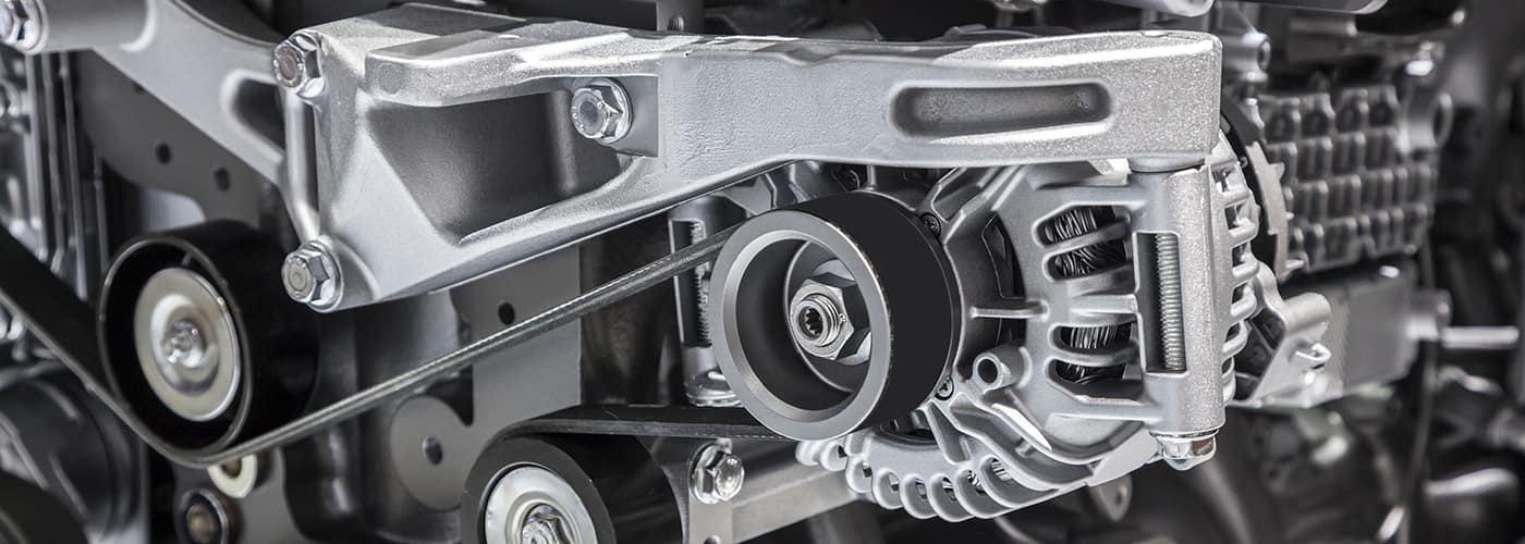
The alternator is made up of the rotor, stator, rectifier, end cap, pulley, etc. Problems in any of these components will result in a poorly working alternator.
As the alternator can be quite tricky to dismantle and install, it is important to make sure that the alternator is indeed faulty before dismantling to find the cause of the further issues. There are usually several ways to diagnose a problem with the component.
Use a DC power supply (6-12V) to excite the alternator's magnetic field winding (ground the negative terminal of the power supply and connect the positive terminal to the alternator's magnetic field terminal). Connect the positive and negative voltmeter pens to the alternator armature terminal and ground respectively.
Turn the pulley as fast as possible by hand, and observe the voltmeter. The normal generator voltage should be 3 to 5V or 5 to 8V.
Wrap a nylon rope of about 1m around the pulley. Clamp the alternator in a vise. Pull the rope hard to make the alternator rotate. The no-load voltage can reach 10-12V or more than 20V.
If the results are in line with the above rule, the alternator is normal. The problem lies in other circuits. If not, the alternator is faulty and should be disassembled to find the cause.
First, check and adjust the tension of the alternator belt, then remove the wires from each terminal. Use another wire to connect the two terminals of the armature ("+") and the magnetic field ("F").
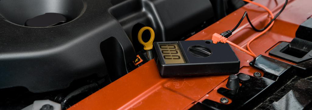
Test the output voltage by the multimeter. Set the multimeter to "DC voltage (0 - 50V)". The red meter pen connects to the generator armature ("+") terminal. The black meter pen connected to the shell, that is, the lap iron.
Start the engine, and touch the magnetic field terminal with the firewire removed from the armature ("+") terminal. Excite the alternator. Remove the wire after a few seconds, and start slowly to increase the engine speed.
Observe the voltage indicated on the multimeter. If the voltage increases gradually with the alternator speed, the alternator under the test is good. The problem lies in other parts.
If the multimeter pointer does not move (no voltage), the alternator is not generating electricity. The internal components or parts may be defective and should be disassembled for inspection.
When the engine stops, turn on the ignition switch. Use one end of the DC test light to connect to the "F" (magnetic field) terminal, the other end to the shell. If the test light is on, the excitation circuit is good. If the test light does not light up, the regulator is faulty.
You can also remove the wires on the "+" and "F" terminals. Connect the test light and start the engine. Increase the engine speed slowly and observe the test light.
If the test light lightens with the increased engine speed, the regulator may be defective. If the light is red, or there is no significant change in luminosity, the alternator is internally faulty.
The causes may be damaged individual diodes, loose phase of the stator winding or short-circuit. Further dismantling for inspection is necessary.
In the case that the alternator is not removed from the vehicle, the multimeter can measure the positive and negative resistance between the terminals. We can initially determine whether the alternator is faulty.
Set the multimeter to the "R×1" range. Measure the positive and negative resistance between magnetic field "F" and the latch, the armature "+" and the latch, the magnetic field "F" and the armature "+" by two pens.
If the resistance between "F" and the latch is large, it may be due to poor contact between the brush and slip ring, loose welding head between the excitation winding and slip ring, or broken circuit of the excitation winding.
If the resistance is very small or 0, it may be a short circuit between the "F" terminal and latch, a short circuit in the excitation winding, a short circuit between slip rings, poor insulation of brush set, etc.
If the resistance between "+" and the latch or "+" and "F" is very small, maybe there is a breakdown short-circuit in the rectifier diode.
The individual rectifier diode is short-circuited or broken if the resistance is close to the specified value. If the resistance value is infinity, the diode is probably broken.
If the positive and negative resistance values are close to each other, the diode may have deteriorated in performance.
The general oscilloscope measures the voltage waveform of the alternator output then show the result based on the display of the waveform. The probable cause of the issue or the damaged component can be accurately and quickly identified.
After confirming that the alternator is faulty, the next step is to disassemble and repair it.
Before disassembling the alternator, we can determine the possible problems by the appearance and necessary tests. We can focus on issues and speed up the overhaul. The main points of inspection before disassembly are as follows.
● Check gap
Swing the pulley all around with your hand to determine if the axial and radial clearance of the front bearing is getting bigger.
● Check resistance
Rotate the rotor and check for bearing resistance, noise, any frictional noise and abnormal rattles between the rotor and stator. If the resistance is too high, remove the brushes and try again to determine whether the resistance is from the brushes or the bearings.
● Check for bent rotor shaft
Rotate the rotor shaft and visually check the size of the pendulum head of the pulley to determine if the rotor shaft is bent.
● Check appearance
Check for cracks and damage to the housing, hanging feet, etc.
● Check rectifier circuit
Set the digital or mechanical multimeter in the "diode" or "resistance". The positive meter pen should be connected to the "E" terminal of the alternator, and the negative meter pen to "B+" or "D+", the value should be less than 1.
If the value is 0 or ∞, the rectifier is damaged. Exchange the meter pen, the value should be ∞. Otherwise, it also indicates that the rectifier is damaged.
● Check magnetic field circuit
Set the multimeter in the "R×1" range. The positive pen connects to the alternator's "E" end. The negative pen connects to the "F" end (the same for the exchange of pens). The normal value should be 3-5Ω.
If the value is 0, the magnetic field winding is short-circuited or lapped. If the value is ∞, the magnetic field winding is broken, and the contact between brush and slip ring is poor.
After the inspection, if the rectifier, brush or brush holder is damaged, they can be replaced without disassembly.
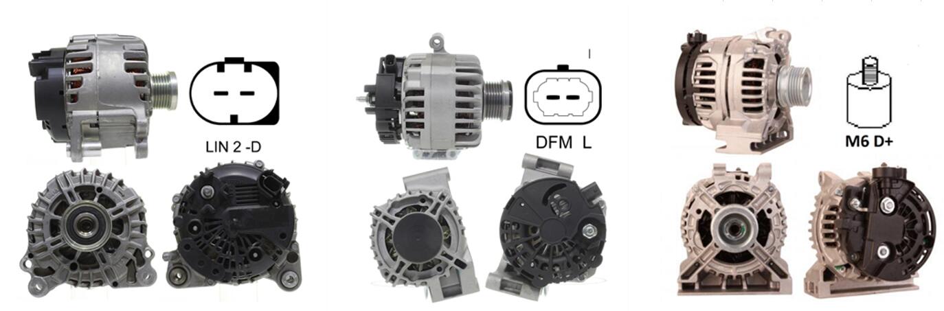
Nowadays, the structure of alternators in various models is different. Therefore, the disassembly sequence is also different. The key points of alternator disassembly are as follows.
Remove dust and oil from the outside of the alternator. Make assembly marks on the front and rear end caps and the core.
Unscrew the fixing nut on the front of the rotor shaft and remove the pulley and fan.
Remove the several fixing bolts from the front end cover. Gently tap on and remove the front end cover with a wooden hammer.
Remove the rear end cap bearing oil seal cover. Unscrew the retaining nut on the rear end cap of the shaft. Use a special tool to jack the rotor shaft out of the rear end cap.
When removing the rotor assembly, take care not to lose the brush spring by allowing it to pop out of the brush holder.
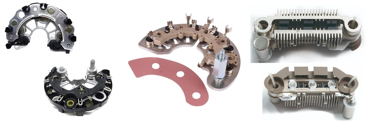
Remove the rectifier element board. Do not remove or lose the insulation pad between the element board and the rear end cover.
Remove the brushes and brush holders. When dismantling, take care not to lose the insulating sleeve on the magnetic field terminals.
 Lauritz Carolsfeld
  March 10, 2022