
Testing is an essential link of engine development. Standard testing methodologies help to troubleshoot failures of the automotive sensors. Well-behaved sensors are vital for daily driving. If automotive sensors have problems, the engine can't work in order. Here are some testing methods for common car sensors.
1. Judge based on signs and symptoms
2. Use the automotive test light
1. Judge based on signs and symptoms
People repair cars based on signs and symptoms of the failure, which is the simplest method to judge whether sensors are bad or not. However, this method has two drawbacks. Firstly, it takes a long time to be specialized. It's impossible to reach a high level in a short time. Secondly, the accuracy of the judgment is low. We always have a high possibility of misjudgment.
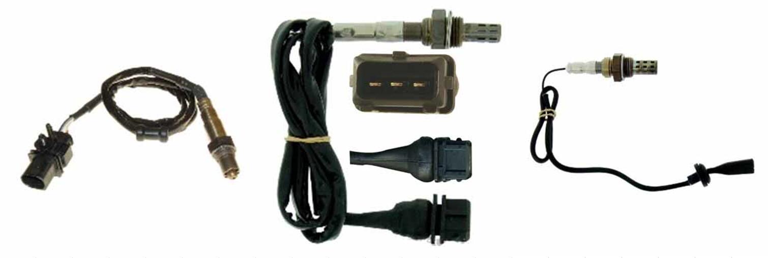
For example, when you repair the Volkswagen engine, if the engine fuel consumption and exhaust pollution increase, with the phenomena of unstable idling, misfiring, surging, it could be the oxygen sensor failure. The failure stops the electronic fuel injection system from getting the oxygen concentration in the exhaust pipe. No feedback on the air-fuel ratio is available. The machine is out of order.
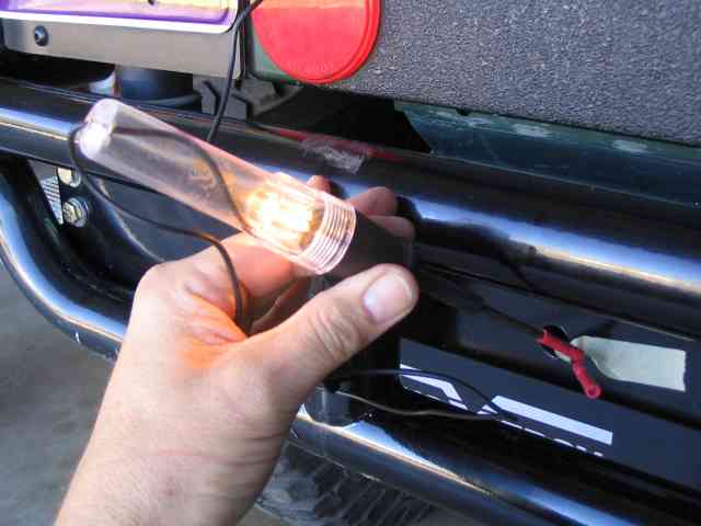
2. Use the automotive test light
There are two types of automotive test lights: the home-made test light and specialized test light. They can either equip with or without a power supply. The home-made test light contacts the 300-500Ω resistor by the LED. The main functions of the test light are:
(1) To check whether the sensor, the electronic control components and the connecting circuit are out of order.
(2) To detect whether the sensor reference voltage supply is regular.
(3) To check whether the sensor has pulse output or whether the ECU has execution signal output based on the LED strobe signal.
(4) To read the fault codes manually for vehicles (If they are with the manual coding self-diagnosis function).
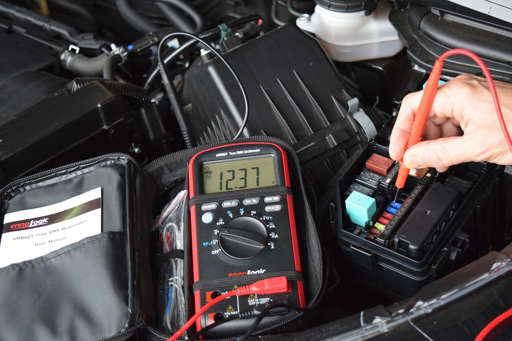
Pointer multimeters are rarely used except for the early manual fault codes reading. In detecting specific components, especially semiconductor components and the ECU circuit, the digital multimeter is obligatory.
The digital multimeter has a high impedance. A small current passes through the component, which avoids burning other components during the measurement.
(1) Resistance Measurement
Resistance measurement mainly detects the variable resistance, potentiometer sensor and the resistance of the magnetoelectric sensor. For the semiconductor components, the measurements should be compared with the standard figures.
For example, the ohmmeter can measure magnetoelectric wheel speed sensors. At room temperature, the expected resistance is in the range of 600 ~ 2300Ω.
Too small resistance explains the short circuit in the coil. Too large resistance explains the poor connection. Very large resistance explains the open circuit.
(2) Voltage Measurement
Active sensors generate their voltage when operating. The voltage measurement is used to check whether sensors, such as oxygen sensors, magneto-electric crankshaft position / camshaft position sensors, knock sensors work properly.
For an example of the magneto-electric ABS wheel speed sensor, remove the socket connector. Let the wheel rotates at the speed of 1 r/s. Measure the voltage between the corresponding terminals of each wheel speed sensor in the mV range.
The normal measurement value should be more than 70mV. Values lower than 70mV indicate the sensor's problem or a too large gap between the sensor and the gear teeth. Then replacing the new parts is inevitable.
(3) Current Measurement
The current measurement applies to new integrated circuit sensors, such as active wheel speed sensors that produce current modulated signals. The multimeter also detects sensors. Set the multimeter to a current range of 200mA or more.
Put the meter pen on one of the output lines; the other output connects the wire normally (mind the polarity of the pointer multimeter). Set up an electric circuit to electrify the ABS, slowly turn the wheel on the sensor side by hand. The normal current fluctuates between 7 and 14mA.
If the value is only fixed at 7mA or 14mA, and the air gap is unadjustable, those indicate a faulty sensor. In addition, when the current value is 0 or more than 100mA, there must be an open circuit or short circuit in the sensor if the multimeter is well connected.
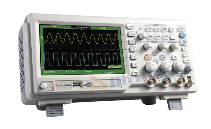
The oscilloscope shows the voltage waveform of the input and output signals in the control system. Technicians analyze and judge the fault of the electronic control system according to the waveform. The oscilloscope shows results faster than the other devices. It is the only detecting instrument that shows the instantaneous waveform.
The oscilloscope is the essential equipment in the fault diagnosis of the electric control system. The oscilloscope test is the most accurate and intuitive method, conducting the output current or voltage of the sensor in the waveform. This method is also the development direction of detecting electrical components.
As an example of the active wheel speed sensor above, the oscilloscope signal input wire connects to the sensor output and signal processing circuit grounding (mind the distinction between the sensor power inlet and signal output).
Turn on the car circuit to energize the system, then slowly turn the sensor installation side of the wheel by hand. Under normal circumstances, the oscilloscope should show a square pulse waveform.
If there is no pulse waveform or inconsistent with the waveform, the installation air gap of the sensor needs adjustment. If there is still no pulse waveform after adjustment, it means that the faulty sensor needs replacement.
The sensor simulator simulates the input signal of the car computer, which replaces real sensors. The method is available for the disconnection of sensors and the normal connection of other circuits.
Technicians judge the condition of sensors based on the disappearance or presence of fault phenomena. The fault diagnosis of sensors and circuits in the electronic control system by this method simplifies the analysis process, shortens the diagnosis time, reduces the economic loss due to mindless replacing parts.
Still don't know good advice on engine maintenance? Feel free to visit our other blog posts. We have several articles about sensors. Take a look!
Common instruments with sensor simulation test functions are the ADD91 signal simulator, the SKS3058 electronic control system analyzer, etc. They simulate the engine control system sensor and show various signals, such as analog voltage signal, frequency signal, DC signal, duty cycle signal, etc.
For example, in the Santana 2000GLi odometer fault test, turn on the ignition switch, find the speed sensor, unplug it. Check the Hall three-wire odometer sensor (One line is 12V, the second is the ground line, the third is the signal line).
If the power supply circuit works, use the simulator. Connect the red meter pen to the signal line pins and artificially input the pulse frequency signal to the signal line.
At this time, ground the black meter pen. The odometer starts. The higher frequency than 100Hz indicates the problem in the sensor.
The sensor substitution is a method of finding faults by replacing suspicious sensors.
The sensor substitution determines the failure position or reduces the fault scope but does not always identify the cause of the fault.
When repairing sensors with this method, it is best to use the same model, type and specification to replace the suspicious sensors temporarily. If the fault doesn't disappear after replacement, it means that the sensors don't cause the fault and that the responsibility lies in other parts.
Using this method to check sensors is simple and straightforward but it requires some maintenance experience and extra well-performed sensors.
Pay attention to two aspects during the replacement: one is not to replace the sensor with different output characteristics. Otherwise it can easily cause misjudgment. Secondly, don't believe in the new sensors, because some new parts aren't well-behaved themselves.
Good quality and affordable car sensors are available at Delcoribo Motor Products, If you are interested, don't hesitate to visit.
 Lauritz Carolsfeld
  June 10, 2021